 by
OVERLOAD AND OTHER PROTECTIONS IN ELECTRICAL SAFETY: Understanding Devices That Prevent Fires, Equipment Damage and Electrical Accidents
Electricity is one of the most essential utilities in any manufacturing facility, commercial establishment or residential building. From operating heavy industrial motors and compressors to running lighting systems, pumps, heaters and sophisticated automation equipment, almost every activity depends on a reliable electrical supply.
However, electricity also presents significant risks when electrical systems are improperly designed, overloaded, poorly maintained or operated without adequate protection.
An overloaded cable, a short circuit, an earth fault or a failed electrical connection can quickly develop into a serious incident. The consequences may include equipment damage, electrical fires, production interruptions, severe burns, electric shock and even fatalities.
This is where electrical protection systems become extremely important.
Electrical protection devices are designed to identify abnormal electrical conditions and disconnect the power supply before the situation develops into a dangerous event.
But are all electrical protection devices designed to perform the same function?
The answer is no.
Overload protection, short-circuit protection, earth-fault protection, residual-current protection, surge protection and other electrical safety mechanisms address different hazards. Understanding their functions is essential for electrical engineers, maintenance professionals, EHS managers, plant managers and anyone responsible for workplace safety.
Let’s understand these protections and their importance in industrial and workplace electrical safety.
1. What Is Electrical Protection and Why Is It Important?
Electrical protection refers to a combination of devices, systems and engineering measures designed to protect people, electrical equipment, cables and installations against abnormal electrical conditions.
Under normal operating conditions, electrical equipment draws current within its designed operating limits. However, abnormal conditions can cause current, voltage or temperature to exceed acceptable levels.
For example:
- A motor may draw excessive current because of mechanical overloading.
- A damaged cable may create a short circuit.
- Damaged insulation may allow current to flow through an equipment enclosure.
- Loose electrical connections may generate excessive heat.
- Lightning or switching operations may produce damaging voltage surges.
Without appropriate protection, these conditions can cause serious consequences.
The main objectives of electrical protection systems are:
- Prevent electrical fires caused by overheating and excessive current.
- Protect electrical cables, motors, transformers and other equipment.
- Minimize the risk of electric shock.
- Prevent damage due to short circuits and earth faults.
- Reduce the possibility of electrical explosions and arc flash incidents.
- Minimize production losses caused by electrical failures.
- Improve the overall reliability of electrical installations.
In simple terms, electrical protection is not just about protecting machines. It is equally about protecting human life.
2. Overload Protection – Understanding the Most Common Electrical Hazard
Overload is one of the most common abnormal electrical conditions in industrial installations.
An electrical overload occurs when equipment or a circuit draws more current than its rated capacity for a period of time.
Unlike a short circuit, an overload does not necessarily involve a direct connection between two conductors. Instead, the connected electrical equipment consumes more current than the circuit is designed to carry.
Common causes of electrical overload
Several conditions can result in electrical overloading:
- Connecting too many electrical appliances to one circuit.
- Operating an electric motor beyond its rated mechanical load.
- Mechanical jamming of pumps, conveyors or rotating equipment.
- Operating equipment with excessive friction or damaged bearings.
- Low voltage conditions that cause certain motors to draw higher current.
- Incorrect equipment selection or undersized electrical cables.
- Simultaneous operation of multiple high-power electrical loads.
What happens during an overload?
Whenever current flows through an electrical conductor, heat is generated due to its electrical resistance.
The heating effect is proportional to the square of the current.
In simple terms:
Heat generation ∝ I²R
Where:
I = Current flowing through the conductor
R = Resistance of the conductor
This means that even a moderate increase in current can produce a significant increase in heat generation.
For example, if current increases by 20%, the heat generated in a conductor, assuming constant resistance, increases by approximately 44%.
If the overload continues, cable insulation may deteriorate, connections may become damaged and surrounding combustible materials may ignite.
How is overload protection provided?
Common overload protection devices include:
A. Thermal Overload Relay
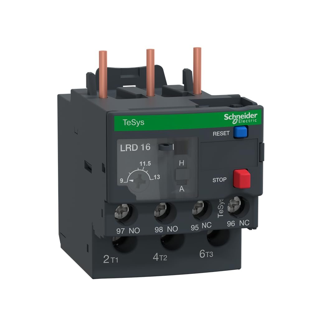
Thermal overload relays are commonly used for protecting electric motors.
They generally operate on the heating effect of current. When the motor draws excessive current for a specified duration, the relay operates and initiates the tripping of the motor contactor.
Most conventional thermal overload relays use a bimetallic mechanism.
These relays are particularly useful in protecting motors against sustained overload conditions.
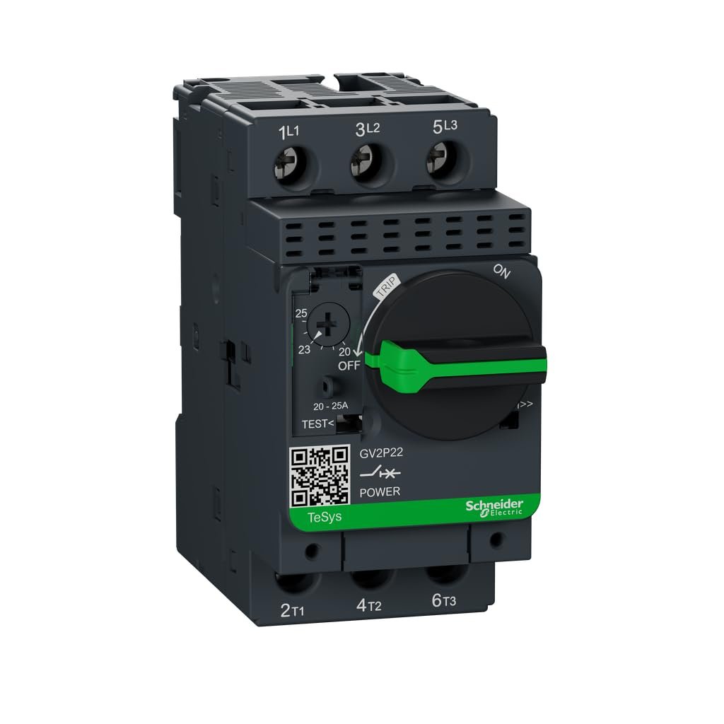
B. Motor Protection Circuit Breaker (MPCB)
An MPCB is specifically designed for motor protection.
Depending on its design, it provides adjustable thermal overload protection and magnetic short-circuit protection.
Some models also provide phase-loss sensitivity and other motor protection features.
C. MCB and MCCB
Miniature Circuit Breakers (MCBs) and Moulded Case Circuit Breakers (MCCBs) can provide overload and short-circuit protection.
Their selection depends on the circuit rating, load characteristics, prospective fault current and application.
An important point to remember is that overload protection must be coordinated with the cable and equipment ratings. Simply installing a higher-rated breaker to avoid frequent tripping can create a serious fire hazard.
3. Short-Circuit Protection – Protecting Against Extremely High Fault Currents
A short circuit is a condition in which current flows through an unintended low-impedance path between conductors or between a conductor and another conductive part.
A short circuit can produce extremely high current within a very short period.
Unlike a typical overload, which may develop gradually, a short circuit can create an immediate and severe electrical fault.
Common causes of short circuits
- Damaged cable insulation.
- Loose or deteriorated electrical connections.
- Incorrect electrical wiring.
- Moisture entering electrical panels or equipment.
- Conductors touching each other due to mechanical damage.
- Failure of electrical components.
- Rodent damage to electrical cables.
- Improper maintenance activities.
What are the consequences of a short circuit?
A short circuit can generate intense heat, electromagnetic forces and electrical arcing.
Potential consequences include:
- Electrical panel fires.
- Cable insulation failure.
- Damage to motors and transformers.
- Arc flash and arc blast incidents.
- Severe burns and fatal injuries.
- Damage to electrical distribution systems.
Short-circuit protection devices
The following devices are commonly used:
1. MCB (Miniature Circuit Breaker)
MCBs are commonly used in residential, commercial and light industrial electrical distribution systems.
They generally provide thermal protection against overloads and magnetic protection against short circuits.
2. MCCB (Moulded Case Circuit Breaker)
MCCBs are commonly used in industrial distribution systems where higher current ratings and greater breaking capacities may be required.
Depending on the design, they may have adjustable overload and short-circuit protection settings.
3. HRC Fuse
High Rupturing Capacity fuses are designed to interrupt high fault currents safely within their specified breaking capacity.
They are widely used in industrial electrical systems, motor circuits and equipment protection applications.
4. Protective Relays
Protective relays continuously monitor electrical parameters and initiate circuit breaker operation when abnormal conditions are detected.
They are commonly used in transformers, generators, feeders and industrial power distribution systems.
An important selection criterion is the breaking capacity of the protective device. It must be adequate for the prospective short-circuit current at the point of installation.
4. Earth-Fault Protection – Preventing Electrical Shock and Equipment Damage
Earth faults are among the most serious electrical hazards in industrial and commercial installations.
An earth fault occurs when an energized conductor comes into contact with an earthed conductive part or another conductive path connected to earth.
For example, if the insulation of a motor power cable becomes damaged, the live conductor may come into contact with the metallic motor body.
If effective earthing and fault protection are not provided, the motor body may remain at a dangerous voltage.
A person touching the motor enclosure could receive an electric shock.
Common causes of earth faults
- Deteriorated cable insulation.
- Damaged electrical equipment.
- Moisture ingress.
- Loose electrical connections.
- Improper installation.
- Damaged electrical appliances.
- Insulation breakdown due to ageing or overheating.
How does earth-fault protection work?
Earth-fault protection detects abnormal current flowing through an unintended earth-fault path.
Depending on the electrical system, protection may be provided through:
- Earth-fault relays.
- Residual-current devices.
- Core-balance current transformers.
- Ground-fault protection incorporated into circuit breakers.
The protective system detects the fault and disconnects the affected electrical circuit.
However, effective earth-fault protection depends on the earthing arrangement, fault-loop impedance, protective-device characteristics and coordination.
A good earthing system provides a low-impedance fault-current path and helps ensure that protective devices operate within the required time.
5. RCCB and ELCB – Protection Against Residual Current and Electric Shock
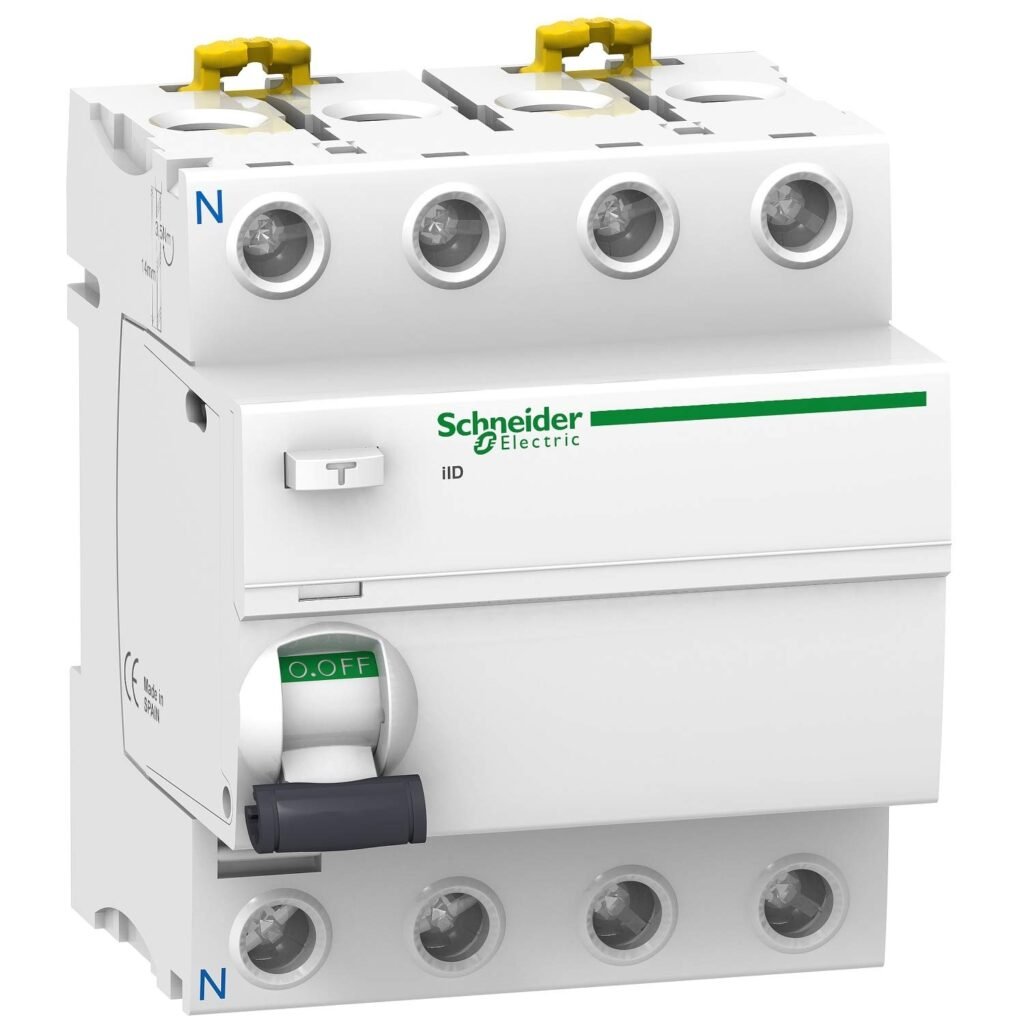
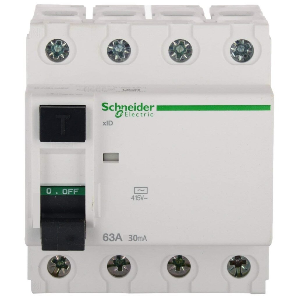
Residual Current Circuit Breakers (RCCBs) are important safety devices used to reduce the risk of electric shock and certain types of electrical fire.
An RCCB continuously monitors the current flowing through the phase and neutral conductors.
Under normal conditions, the outgoing and returning currents should be balanced.
If some current escapes through an unintended path, such as a person or an earth connection, an imbalance occurs.
The RCCB detects this difference and disconnects the electrical supply when the residual current exceeds its specified operating threshold.
Where are RCCBs useful?
- Residential electrical distribution boards.
- Commercial buildings.
- Laboratories.
- Wet processing areas.
- Utility rooms.
- Industrial installations.
- Portable electrical equipment circuits.
Important difference between RCCB and MCB
An RCCB and an MCB do not provide the same protection.
An MCB protects against overload and short-circuit current.
An RCCB protects against residual current or earth leakage.
A standard RCCB does not provide overload or short-circuit protection. Therefore, it must be protected by an appropriately selected overcurrent protective device unless the device is a combined protective unit.
What about ELCB?
The term Earth Leakage Circuit Breaker (ELCB) is commonly used for earth-leakage protection devices.
Historically, voltage-operated ELCBs were used. Modern residual-current-operated devices detect current imbalance and are commonly referred to as RCCBs or RCDs.
It is important to identify the actual device type rather than relying only on the terminology used at a facility.
6. RCBO – Combining Multiple Electrical Protections
An RCBO (Residual Current Circuit Breaker with Overcurrent Protection) combines the functions of an RCCB and an MCB.
It generally provides:
- Overload protection.
- Short-circuit protection.
- Residual-current protection.
This makes it useful where individual circuit protection and residual-current protection are required in a single device.
For example, an RCBO can be installed to protect an individual socket circuit, lighting circuit or selected equipment circuit.
The major advantage is that a fault in one protected circuit can be isolated without necessarily interrupting other circuits.
However, correct selection of the RCBO operating characteristics, residual-current sensitivity and type is essential for the connected equipment and application.
7. Surge Protection – Protecting Equipment Against Voltage Spikes
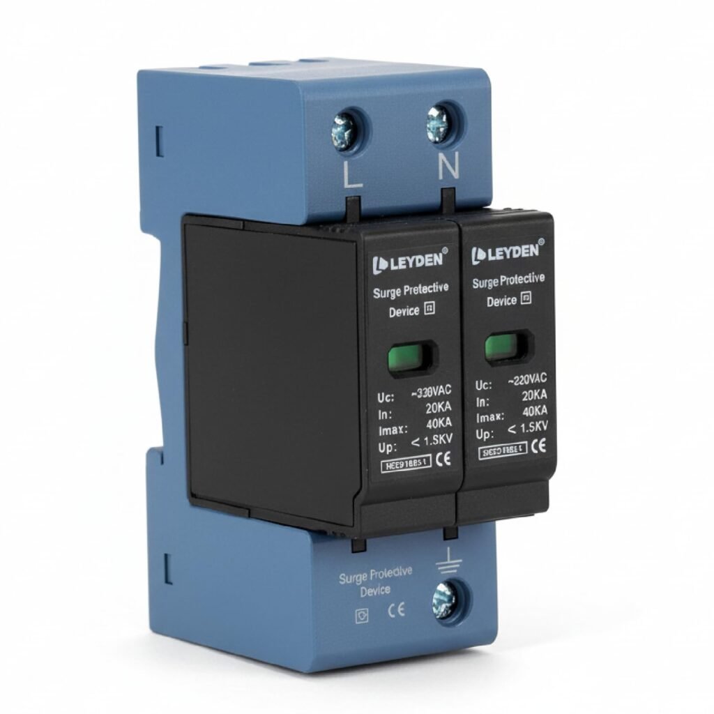
Not all electrical hazards involve excessive current.
Sometimes, the voltage supplied to equipment can increase suddenly beyond its normal operating range.
These temporary voltage increases are called transient overvoltages or voltage surges.
They can occur due to:
- Lightning strikes.
- Switching operations.
- Utility network disturbances.
- Inductive load switching.
- Electrical system faults.
Sensitive electronic equipment, PLCs, automation systems, computers, communication equipment and instrumentation may be damaged by these voltage transients.
Surge Protection Device (SPD)
An SPD is designed to limit transient overvoltages and divert surge current away from protected equipment.
Depending on the installation, different types of SPDs may be used:
Type 1 SPD: Used where protection against direct lightning current is required, typically at the origin of an installation with an appropriate lightning protection arrangement.
Type 2 SPD: Commonly installed in distribution boards to protect against induced lightning surges and switching transients.
Type 3 SPD: Used close to sensitive equipment as supplementary protection.
The SPD must be selected according to the installation, earthing arrangement, expected surge exposure and coordination requirements.
It is also important to remember that an SPD does not replace overload, short-circuit or earth-fault protection.
8. Phase Failure, Phase Sequence and Voltage Protection
Three-phase electrical systems are commonly used in manufacturing plants to operate motors, compressors, pumps, conveyors and other industrial equipment.
Abnormal phase conditions can damage equipment and create unsafe operating conditions.
A. Phase Failure Protection
Phase failure occurs when one of the three phases is interrupted.
If a three-phase motor continues operating under single-phasing conditions, it may draw excessive current in the remaining phases and overheat.
Phase failure protection detects the loss of a phase and initiates a trip to protect the motor.
B. Phase Sequence Protection
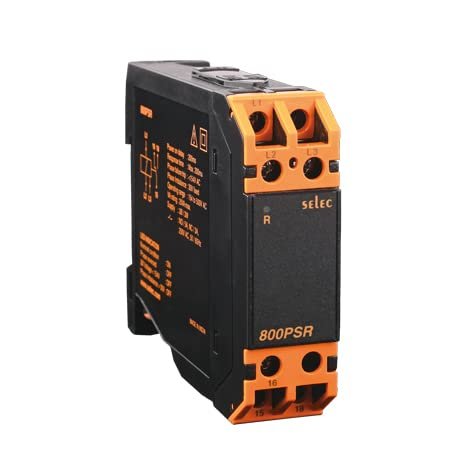
Phase sequence refers to the order in which the three phases are supplied.
An incorrect phase sequence can cause certain three-phase motors to rotate in the opposite direction.
This can be particularly dangerous for pumps, compressors, conveyors and other machinery where the direction of rotation is critical.
A phase-sequence relay helps prevent operation under an incorrect phase sequence.
C. Under-Voltage Protection
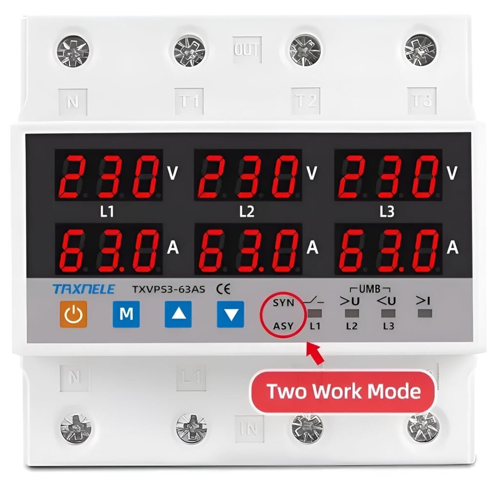
Under-voltage occurs when supply voltage falls below the acceptable operating limit.
It can cause problems with motors, contactors and other electrical equipment.
Under-voltage protection disconnects or prevents equipment operation when voltage falls below a specified threshold.
D. Over-Voltage Protection
Over-voltage occurs when supply voltage exceeds the acceptable operating range.
It may damage insulation, electronic components and connected equipment.
Over-voltage relays or appropriate voltage-monitoring devices can disconnect equipment when abnormal voltage conditions are detected.
9. Motor Protection – More Than Just Overload Protection
Electric motors are among the most important electrical assets in manufacturing facilities.
They operate pumps, agitators, compressors, blowers, cooling towers, conveyors and production machinery.
A motor failure can interrupt production and create significant maintenance costs.
Motor protection should therefore address several possible failure conditions.
Important motor protection functions include:
- Overload protection.
- Short-circuit protection.
- Phase failure protection.
- Phase imbalance protection.
- Earth-fault protection.
- Locked-rotor protection.
- Under-voltage protection.
- Over-temperature protection.
- Bearing temperature monitoring, where appropriate.
Why is motor overload protection important?
Consider an industrial centrifugal pump.
If the pump develops excessive mechanical resistance, the motor may draw more current than its rated operating current.
If the motor continues running under this condition, the winding temperature increases.
Over time, insulation deterioration can result in motor failure.
A properly selected thermal overload relay or electronic motor protection relay helps detect this condition and disconnect the motor before serious damage occurs.
However, the protective device must be selected according to the motor nameplate, starting characteristics, duty cycle and manufacturer recommendations.
10. Transformer Protection – Safeguarding Critical Electrical Assets
Transformers are essential components of electrical distribution systems.
They operate under varying load conditions and must be protected against internal and external faults.
Important transformer protection systems include:
- Overcurrent protection.
- Earth-fault protection.
- Differential protection.
- Restricted earth-fault protection.
- Buchholz relay, where applicable.
- Winding temperature protection.
- Oil temperature protection.
- Pressure relief devices.
- Overfluxing protection, where applicable.
Differential protection compares currents entering and leaving the protected transformer zone.
A significant difference may indicate an internal fault, resulting in a trip command.
Buchholz relays are used in applicable oil-filled transformers equipped with a conservator system. They detect gas accumulation and abnormal oil movement associated with certain internal faults.
Transformer protection must be designed according to transformer capacity, construction, voltage level and applicable electrical standards.
11. Arc Flash Protection – A Critical but Often Overlooked Electrical Hazard
Arc flash is one of the most dangerous electrical hazards in industrial environments.
An arc flash occurs when electrical energy is released through an electrical arc.
It can produce extremely high temperatures, intense light, pressure waves and molten metal particles.
Arc flash incidents may occur due to:
- Electrical insulation failure.
- Incorrect switching operations.
- Loose connections.
- Equipment contamination.
- Incorrect maintenance practices.
- Accidental contact with energized components.
- Improperly performed electrical work.
How can arc flash risks be controlled?
Arc flash risk management should include:
- Proper electrical system design.
- Appropriate short-circuit protection.
- Protective relay coordination.
- Arc flash risk assessment where required.
- Appropriate electrical equipment maintenance.
- Restricted access to electrical rooms.
- Safe electrical work procedures.
- Lockout/Tagout (LOTO).
- Suitable arc-rated PPE based on the risk assessment.
- Competent and authorized electrical personnel.
It is important to understand that conventional overload protection alone does not necessarily prevent arc flash incidents.
The incident energy and potential exposure must be assessed, and appropriate engineering and administrative controls must be implemented.
12. Electrical Protection Devices – Quick Comparison
| Protection device | Main protection |
|---|---|
| MCB | Overload and short circuit |
| MCCB | Overload and short circuit |
| Thermal Overload Relay | Motor overload |
| MPCB | Motor overload and short circuit, depending on model |
| RCCB | Residual current / earth leakage |
| RCBO | Overload, short circuit and residual current |
| HRC Fuse | Overcurrent and short circuit |
| Earth Fault Relay | Earth fault |
| SPD | Transient voltage surges |
| Phase Failure Relay | Phase loss |
| Phase Sequence Relay | Incorrect phase sequence |
| Differential Relay | Internal electrical faults within a protected zone |
| Buchholz Relay | Certain internal faults in applicable oil-filled transformers |
The above comparison is intended as a general guide. Actual protection depends on the device design, settings and installation arrangement.
13. Common Mistakes in Electrical Protection Systems
Even when electrical protection devices are installed, inadequate selection, incorrect settings or poor maintenance can compromise their effectiveness.
Some common mistakes observed in industrial installations include:
1. Increasing breaker ratings to avoid frequent tripping
When a breaker trips repeatedly, some facilities replace it with a higher-rated breaker without investigating the root cause.
This is a dangerous practice.
The original tripping may be due to an overloaded circuit, faulty equipment or damaged insulation.
Increasing the breaker rating without checking cable capacity and equipment requirements may create an overheating and fire hazard.
2. Assuming RCCB protects against every electrical fault
An RCCB does not provide overload and short-circuit protection unless combined with those functions in an RCBO.
3. Ignoring loose electrical connections
Loose connections can generate localized heating and may eventually cause insulation failure or fire.
Regular inspection and appropriate thermal scanning can help identify developing problems.
4. Improper earthing
An effective earthing system is essential for safe fault-current paths and proper operation of protective devices.
5. Incorrect relay settings
Protective relay settings must be based on engineering calculations and the characteristics of the protected equipment.
Incorrect settings may cause unnecessary trips or inadequate protection.
6. Neglecting periodic testing
Electrical protection devices should not simply be installed and forgotten.
Their mechanical operation, electrical characteristics, trip settings and functional performance should be verified at appropriate intervals.
14. Electrical Safety Inspection Checklist for Manufacturing Plants
An effective electrical safety inspection programme should cover electrical panels, motors, transformers, cables and distribution systems.
The following checklist can be used by EHS and electrical maintenance teams as a starting point.
Electrical panel inspection
- Electrical panels are properly enclosed and secured.
- Circuit breakers are correctly rated.
- Overload and short-circuit protection is available.
- RCCB/RCBO protection is provided where required.
- Panel doors and covers are properly maintained.
- No exposed live parts are accessible.
- Electrical panel identification is available.
- Cable entries are properly sealed.
- No combustible materials are stored near electrical panels.
- Thermography is conducted as part of the maintenance programme.
Motor protection inspection
- Motor overload relays are installed where required.
- Relay settings match approved motor protection calculations.
- Phase failure protection is provided where required.
- Motor earthing is satisfactory.
- Motor terminal boxes are properly enclosed.
- Cable insulation is in good condition.
- Motor temperature and abnormal vibration are monitored where appropriate.
General electrical safety
- Earthing continuity is verified.
- Insulation resistance testing is conducted.
- Protective devices are periodically tested.
- Electrical single-line diagrams are updated.
- Electrical maintenance is performed by authorized personnel.
- LOTO procedures are followed.
- Electrical rooms have restricted access.
- Electrical safety training is provided.
- Defects identified during inspections are tracked to closure.
15. Electrical Protection and Legal Compliance in India
In India, electrical safety requirements are addressed through the Central Electricity Authority (Measures relating to Safety and Electric Supply) Regulations, 2023.
These regulations cover electrical installations, electrical equipment and the responsibilities of persons involved in the generation, transmission, distribution, supply and use of electricity.
The regulations address important aspects such as:
- Safe design and installation of electrical equipment.
- Protection against abnormal electrical conditions.
- Earth-fault and earth-leakage protection.
- Competency and authorization of electrical personnel.
- Safe operation and maintenance.
- Inspection and testing of electrical installations.
- Personal protective equipment and electrical work precautions.
The regulations require appropriate overcurrent protection and earth-fault or earth-leakage protection to automatically disconnect supply under specified abnormal conditions.
Manufacturing organizations should review their electrical installations against the applicable CEA requirements, relevant Indian Standards, National Electrical Code and other applicable statutory requirements.
Electrical installation work, including additions, alterations and repairs, must also comply with the applicable requirements for licensed contractors and competent personnel.
Organizations should consult the current regulations and applicable state requirements to establish their compliance obligations.
16. What Should EHS Managers and Plant Leaders Focus On?
Electrical safety should not be treated as the sole responsibility of the electrical maintenance department.
It is an important part of the overall EHS management system.
EHS managers and plant leaders should establish a structured electrical safety programme that includes:
Electrical risk assessment: Identify electrical hazards associated with equipment, electrical rooms, temporary connections and maintenance activities.
Engineering controls: Ensure appropriate overload, short-circuit, earth-fault, surge and other protections are provided.
Preventive maintenance: Establish inspection, testing and preventive maintenance schedules for critical electrical assets.
LOTO implementation: Ensure equipment is properly isolated, locked and verified de-energized before electrical maintenance.
Competency development: Ensure electrical work is performed only by authorized and competent personnel.
Incident investigation: Investigate electrical trips, overheating, cable damage, electrical fires and near misses to identify root causes.
Management review: Include electrical safety performance in periodic plant EHS reviews.
Useful leading indicators include:
- Percentage of electrical preventive maintenance completed on time.
- Percentage of electrical protection devices tested as scheduled.
- Number of overdue electrical safety observations.
- Percentage of critical electrical defects closed within target timelines.
- Completion of electrical thermography surveys.
- Electrical safety training completion.
- Number of repeated electrical tripping incidents.
Monitoring these indicators helps shift electrical safety management from a reactive approach to a preventive approach.
Conclusion: Electrical Protection Is an Investment in Life Safety
Overload protection, short-circuit protection, earth-fault protection, residual-current protection and surge protection each play a different role in maintaining electrical safety.
No single device can protect an entire electrical installation against every possible hazard.
An effective electrical protection system requires the right combination of properly selected protective devices, correct engineering design, reliable earthing, periodic testing, preventive maintenance and competent personnel.
For manufacturing facilities, electrical safety must go beyond simply installing MCBs, MCCBs and RCCBs.
The real objective should be to identify abnormal conditions early, prevent escalation and ensure that electrical faults are safely isolated before they cause injuries, fires or equipment damage.
Remember one important principle:
Electrical protection devices are not just electrical components installed inside a panel. They are critical life-safety barriers that protect people, equipment and business operations.
A well-designed and properly maintained electrical protection system can make a significant difference between a minor electrical fault and a major industrial accident.
Make electrical protection a priority, not an afterthought.
Frequently Asked Questions (FAQs)
1. What is the difference between overload and short circuit?
An overload occurs when an electrical circuit draws more current than its designed capacity for a period of time. A short circuit occurs when current flows through an unintended low-impedance path, generally resulting in a very high fault current.
2. Which device is used for overload protection?
MCBs, MCCBs, thermal overload relays and motor protection circuit breakers are commonly used, depending on the application.
3. Does an RCCB protect against overload?
No. A standard RCCB provides residual-current protection but does not provide overload or short-circuit protection. An RCBO combines these protection functions.
4. What is the purpose of an earth-fault relay?
An earth-fault relay detects abnormal current flowing through an earth-fault path and initiates disconnection of the affected circuit through a circuit breaker.
5. Why is overload protection important for electric motors?
Overload protection prevents motors from operating under sustained excessive-current conditions that can cause overheating, insulation deterioration and winding failure.
6. What is the purpose of a surge protection device?
An SPD limits transient overvoltages and diverts surge current to help protect electrical and electronic equipment from voltage surges.
7. How frequently should electrical protection devices be tested?
Testing frequency should be established through applicable statutory requirements, relevant standards, manufacturer recommendations, risk assessment and the facility’s preventive maintenance programme. Critical protective devices should have documented inspection and functional-testing records.
8. Can a higher-rated MCB solve repeated tripping problems?
Not necessarily. Repeated tripping may indicate overload, short circuit, earth leakage or equipment malfunction. The root cause must be identified before changing the protective device rating.
9. What is the difference between MCB, MCCB and MPCB?
An MCB is generally used for lower-current distribution circuits. An MCCB is designed for higher-current applications and may offer adjustable protection. An MPCB is specifically designed for motor circuit protection, with features depending on its model.
10. What is the most important electrical safety protection in a manufacturing plant?
There is no single most important device. A properly engineered combination of overcurrent protection, earth-fault protection, residual-current protection where required, effective earthing, equipment-specific protection and safe isolation procedures is essential.
Disclaimer: This article is intended for electrical safety awareness and general educational purposes. Electrical protection design, device selection, settings and installation must be performed or verified by qualified electrical professionals in accordance with applicable statutory requirements, relevant standards and manufacturer recommendations.
🔁 Readers also enjoyed these blog posts:
- Safety Management’s Role: The Unsung Hero Behind Every Successful Organization
- Safety Management and Its Responsibilities: Protecting People, Preventing Hazards, and Promoting a Culture of Care
- Benchmarking for Safety Performance: A Key to Continuous Improvement
“Start Your Website Journey Today – Exclusive Hostinger Discounts!”