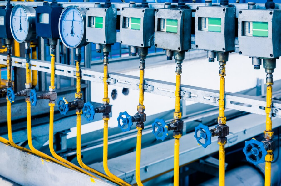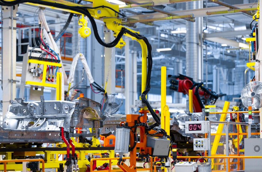
INTRODUCTION
INSTRUMENTS ARE INCORPORATED IN A PROCESS PLANTS TO:
Measure
Indicate
Record
Control
various process parameters like temperature, pressure, flow, concentration etc…rendering the smooth & safe as well operation.
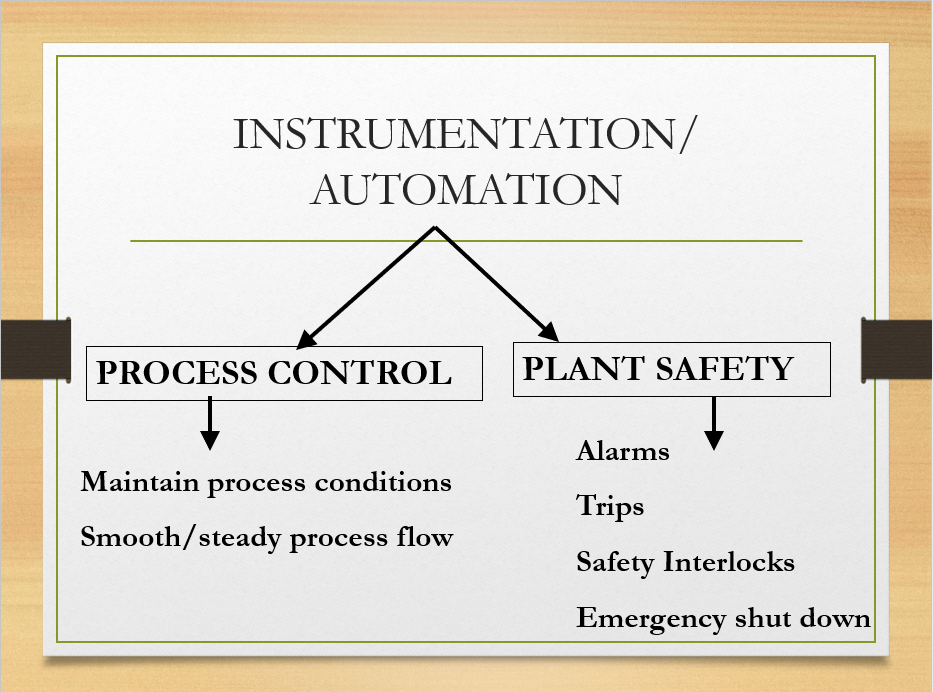
Alarms

•The fundamental purpose of alarm annunciation is to alert the operator to deviations from normal operating conditions, i.e. abnormal operating situations.
•The ultimate objective is to prevent, or at least minimize, physical and economic loss through operator intervention in response to the condition that was alarmed.
•The fundamental purpose of dynamic alarm annunciation is to alert the operator to relevant abnormal operating situations. They include situations that have a necessary or possible operator response to insure:
•Personnel and Environmental Safety,
•Equipment Integrity,
•Product Quality Control.
•Alarms should be both audible & visible.
•Some commonly found applications of alarm system are:
•Alarms for limit of operating parameters like high/low pressure, temperature, level…
•Smoke alarms
•Gas detectors
•Fire alarms
Ultimately, alarms give warnings providing opportunity for MITIGATION & does not take actions against abnormality.
Safety Interlocks
•Interlock circuits and their components should be designed to actuate the final devices (e.g. control valves) in the direction required to cause the process to fail-safe upon loss of power.
•A good principle to follow is this: “every system is to fail to its lowest energy state, or to a state away from its critical operating limit”. In other words, each process should be analyzed to determine the major source of energy for operation, e.g. steam to reboiler, exothermic (i.e. heat releasing) reaction.
•Decreasing the amount of energy reduces the risk of an equipment exceeding the design limits, or at least minimizes the potential damage if the limits are exceeded. For the reboiler example, a fail-safe design would trip the steam supply to the reboiler. In the exothermic reaction example, a fail-safe design would trip the feed to the reactor and/or the fuel to the reactor heater.

•In a manual trip, the interlock system is manually actuated from a switch or pushbutton, which may be located on a local panel in the field or in the control room. A manual trip allows an operator to trip the system independently of the interlock system in the event of a hazardous situation developing.
•An automatic trip, as the name implies, is automatically activated when a hazardous situation is detected. A common example is the de-energizing of a solenoid valve that fails a control valve to its safe position.
BYPASSING INTERLOCKS
•Interlocks may sometimes required to be bypassed in case of start-up, small anticipated interruptions, faulty feedbacks from instruments.
•Bypasses may also be necessary in order to test components on-line without tripping protected equipment.
•A strict protocol should be followed when bypassing of interlock is attempted. Usually only authorized personnel are permitted to bypass any interlock. This can be achieved either using a key or manually operated switch. When a bypass is initiated, an alarm will be triggered.
Safety Interlocks
•Safety interlock is a system of sequential operation to trip/stop:
•Preventing overflow/spillage of hazardous chemical
•To shut down plant safely
•To release excess pressure
•To avoid run-away reaction
•To prevent toxic release/fire/explosion
•To avoid reach of extreme condition leading to severe accidents/incidents.
DCS
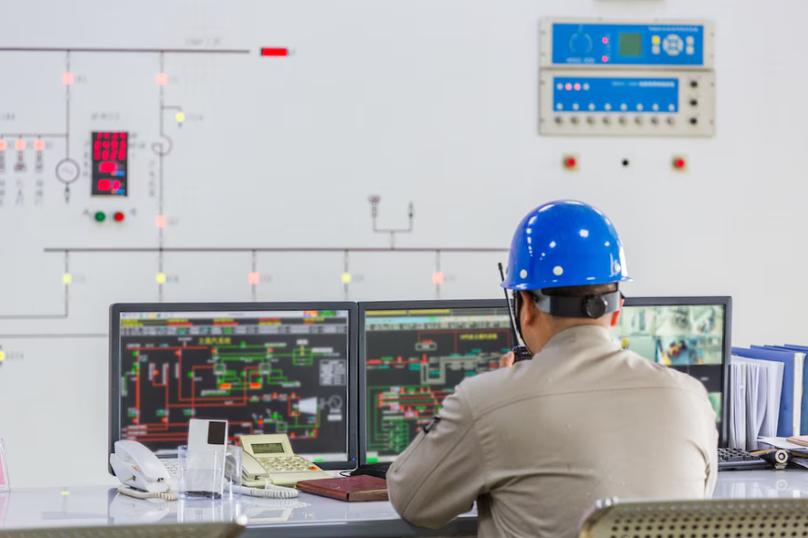
•A distributed control system (DCS) refers to a control system usually of a manufacturing system, process or any kind of dynamic system, in which the controller elements are not central in location (like the brain) but are distributed throughout the system with each component sub-system controlled by one or more controllers. The entire system of controllers is connected by networks for communication and monitoring.
•DCSs are connected to sensors and actuators and use setpoint control to control the flow of material through the plant. The most common example is a setpoint control loop consisting of a pressure sensor, controller, and control valve. Pressure or flow measurements are transmitted to the controller, usually through the aid of a signal conditioning input/output (I/O) device. When the measured variable reaches a certain point, the controller instructs a valve or actuation device to open or close until the fluidic flow process reaches the desired setpoint.
•DCS’s were designed to control processes, not discrete operations.
•As such, a large number of the inputs and outputs are analog like a 4-20mA signal or 0-10V signal. These signals generally represent temperature, flow, pressure, pH, conductivity or some other process variable.
•The “distributed” part of the name is indicating that the control functions are spread out among many different hardware parts. Using one big mainframe computer to control a plant was attempted back in the ’60s but it soon became clear that one bug, hang-up, or failure could cause the whole plant to shutdown. Distributed control gives a safety margin!
PLC
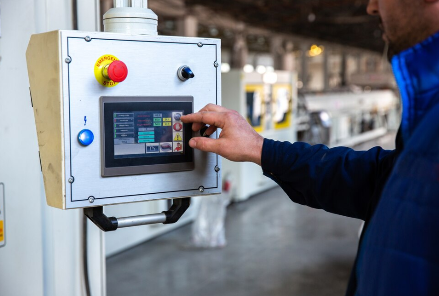
•Small digital logic controller typically utilized to replace hard-wired relay.
•Especially for discrete control of manufacturing processes.
•A PLC (i.e. Programmable Logic Controller) is a device that was invented to replace the necessary sequential relay circuits for machine control. The PLC works by looking at its inputs and depending upon their state, turning on/off its outputs. The user enters a program, usually via software, that gives the desired results.
•PLCs are installed for sequential operation i.e. interlocks system.
